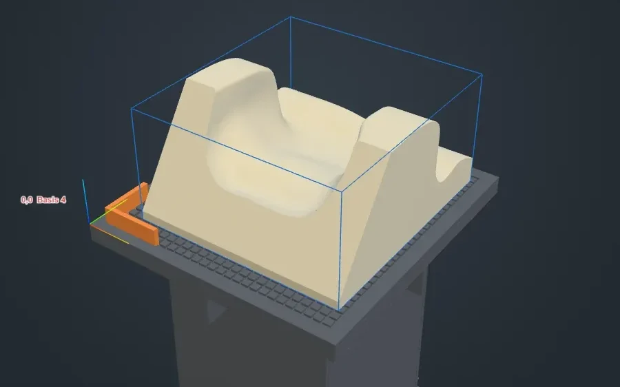
In production · seat cell
SeatStudio
Turns the shop's CAM program into a KUKA program: load, place on the table, check, send.
Old 3D printers took hours of setup. With a Bambu you upload the file, press print and it works. We are building that for manufacturing: you upload a 3D model, the robot measures itself, prints the part if it needs to and mills it to size. Nobody programs the robot.
Prototypes, moulds, seat foams, fixtures and the first parts of every series all need a program, a set-up and test runs first.
The people around it are: CAM and robot programming, set-up, test runs and hand work, paid again for every new part.
One at a time, on standard industrial robots. In our seat cell the robot programmer is already gone.
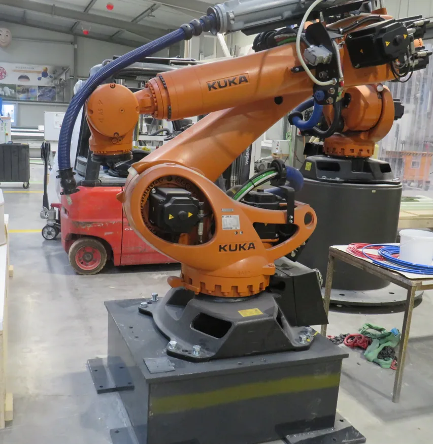
At ACCENTFORM in Nienstädt, a KUKA KR 210 on a linear rail mills seat foams for customer orders. The shop's CAM program goes into our software, a checked KUKA program comes out, and the robot runs it. There is no robot programmer in between.
SeatStudio is the cell's app, written by us. The operator loads the job and places it on the table. Everything a robot programmer used to do happens in the five steps below.
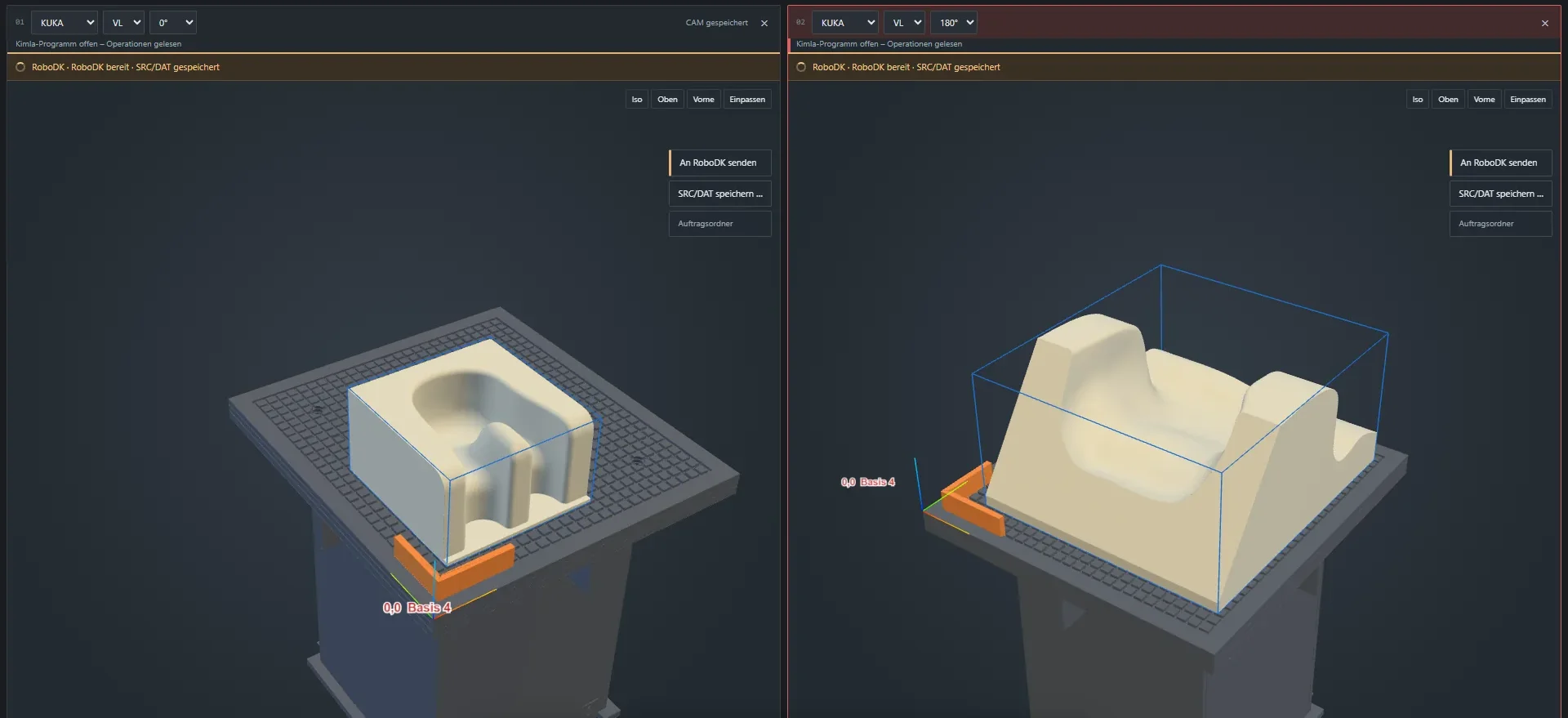
The part's 5-axis CAM program, as the shop already makes it for its CNC machines.
The part goes on the table grid, corner on the locator, turned to suit the robot.
For every move, a tool angle the robot can reach, smooth from one move to the next.
Reach, joint limits and collisions of robot, spindle, holder, part and table.
The KUKA program goes to the controller and the robot cuts. Nobody edits a line.
The table every part is held on: two ABS plates from our own CAD, milled on the shop's 5-axis CNC, threads cut by hand, screwed together and set on the cell's grid.
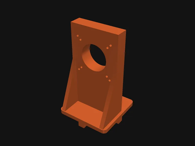
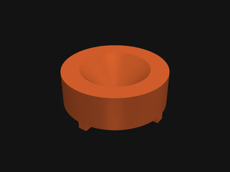
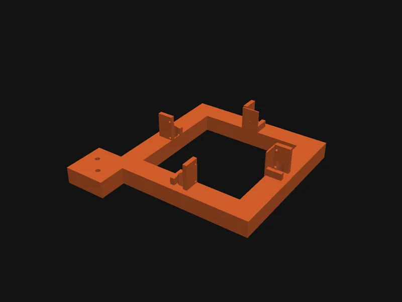
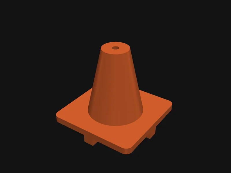
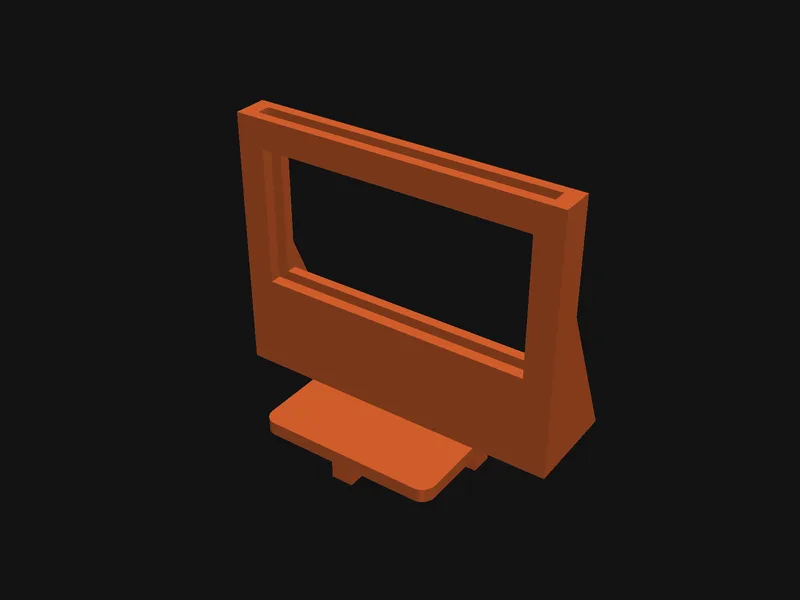
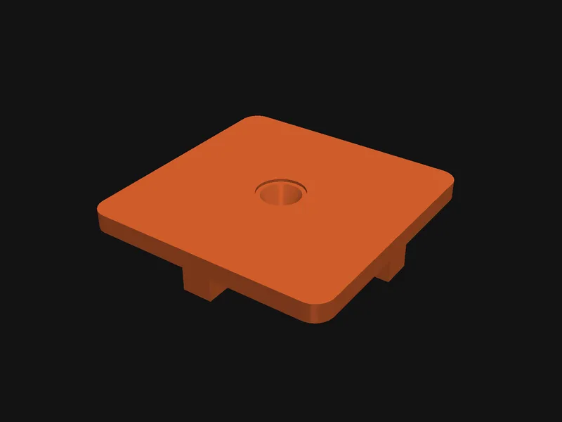
The holders for measuring the tools are designed here, printed and keyed into the table grid. The laser frame stands on a welded steel stand.
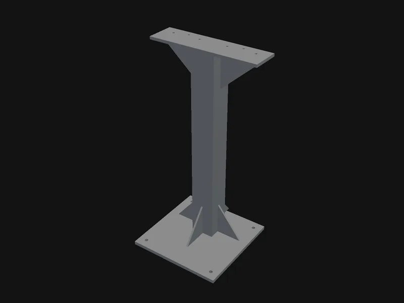
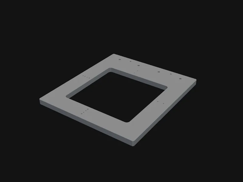
On the shop's 5-axis gantry, our software nests the boards, writes a program for every sheet, checks it and posts it for the machine. Fixtures, patterns and prototype parts come off the sheet ready to put together.
Render of a fixture job on the KIMLA BFN 2141.
No more teaching the tool point by eye. Below, the real run: a camera watches the D60 cutter while the robot turns it through 50 poses, and the new tool point goes onto the controller. It has run with it since 13 Oct.
Camera footage of the cell, sped up. Three ways to measure, each built from catalogue parts and printed holders keyed into the table grid:
The tool passes two crossed beams. Where they break gives its axis, and the crossing gives its point.
Two cameras at 90° watch the tip against lit panels while the robot turns it. Nothing is touched.
A ball cutter seats in a printed cone and stays seated as the robot tilts it: the proof for the ball centre.
Renders from the cell's CAD model.
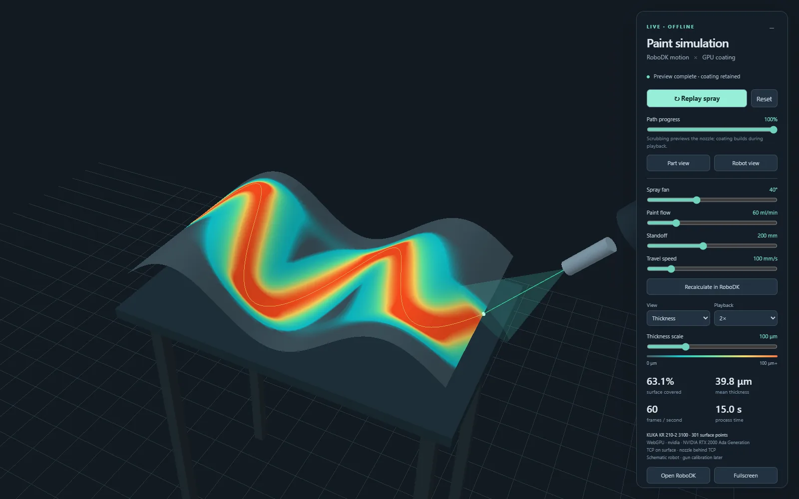
A KUKA KR 210 R3100 sprays gelcoat into moulds. The spray paths come from the mould's CAD, and the coat thickness is simulated on the GPU before the robot moves.
All of it written by us. Some of it runs on customer jobs today, some is being tested in the cell, and the rest is on its way to the same cells.
Turns the shop's CAM program into a KUKA program: load, place on the table, check, send.
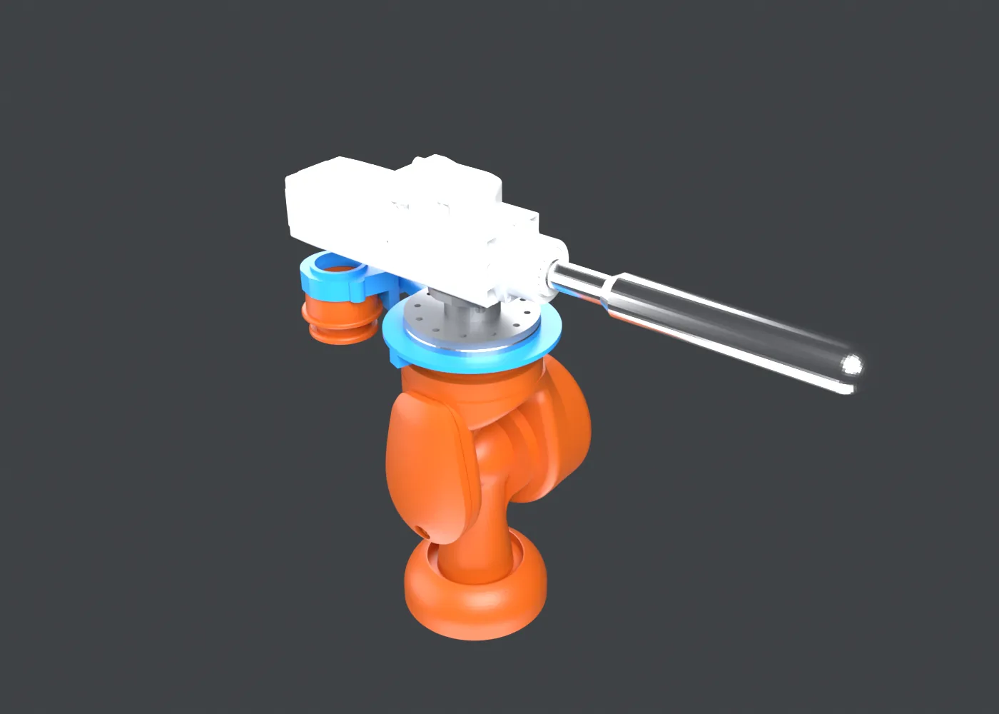
Every move tested for reach, joint limits and collisions of robot, spindle, holder, part and table before the controller sees it.
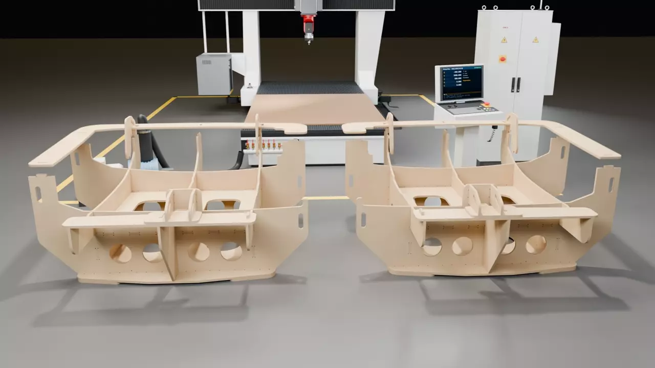
Nests the boards of a fixture on the sheets, writes and checks one program per sheet and posts it for the gantry.
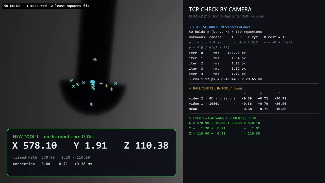
A camera watches the cutter while the robot turns it. The measured tool point has been on the controller since 13 Oct.
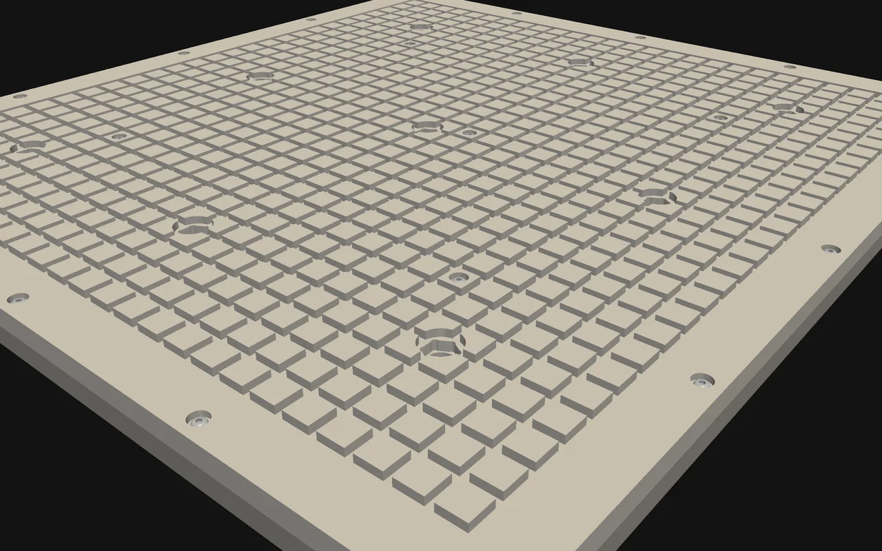
Vacuum table, locators, camera and laser holders: designed in our CAD, milled and printed in the shop.
Gelcoat paths from the mould's CAD, with the coat thickness simulated on the GPU before the robot moves.
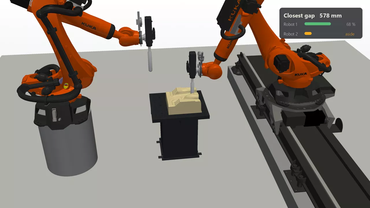
Splits one program between two robots and holds one back whenever the arms would come within 100 mm.
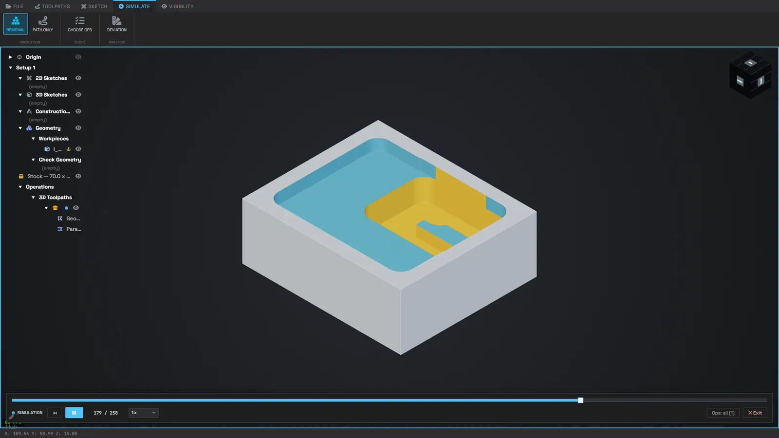
Design, toolpaths and print layers in one app in the browser, so a part goes from model to machine in one place.
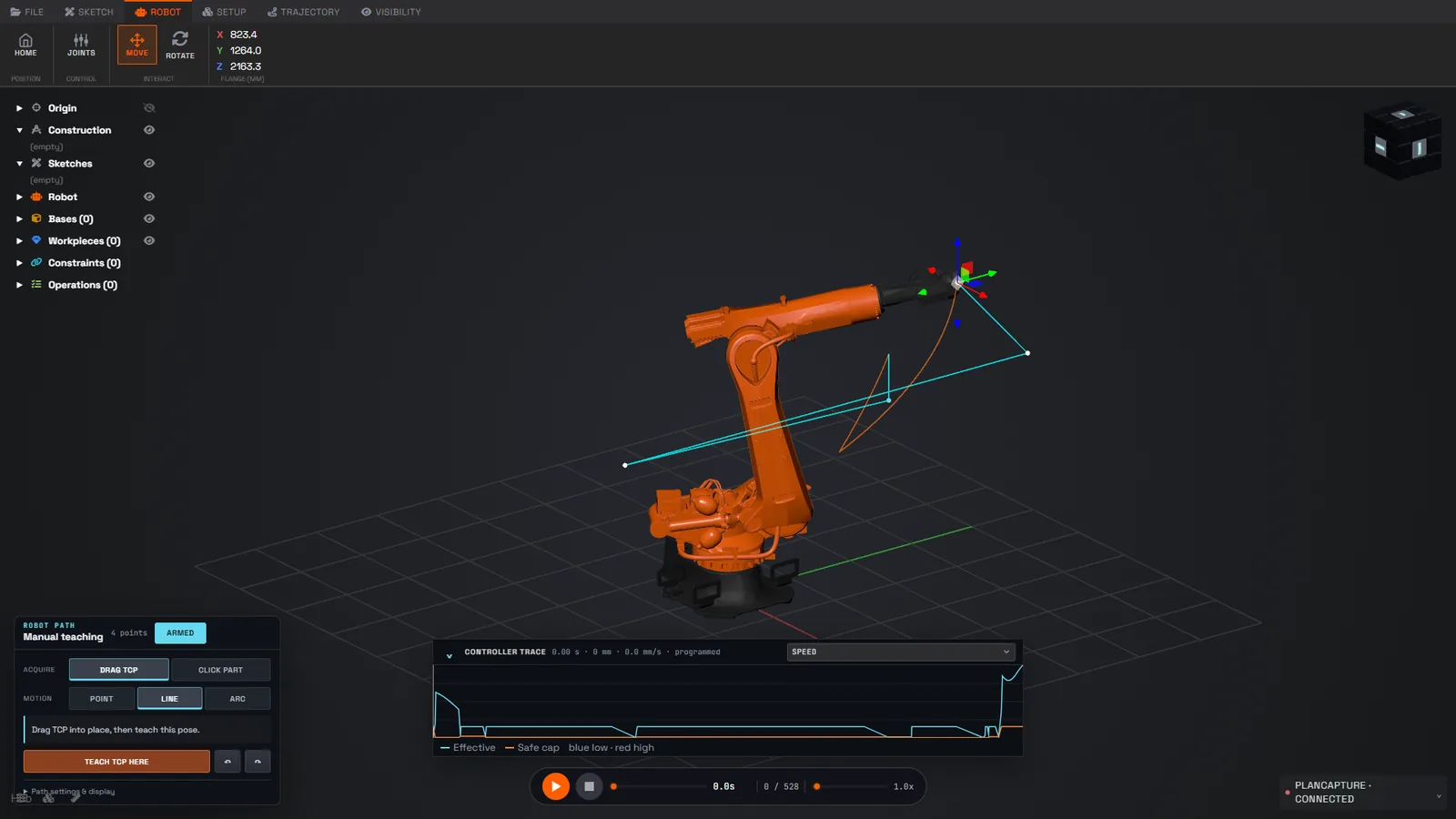
Robot paths with the controller's own trace, and finite elements on the GPU checked against CalculiX.
Our own CAM on implicit geometry. It works on the part as a signed distance field, not a mesh, and computes roughing and finishing paths with the whole tool, holder included, checking the holder against the part.
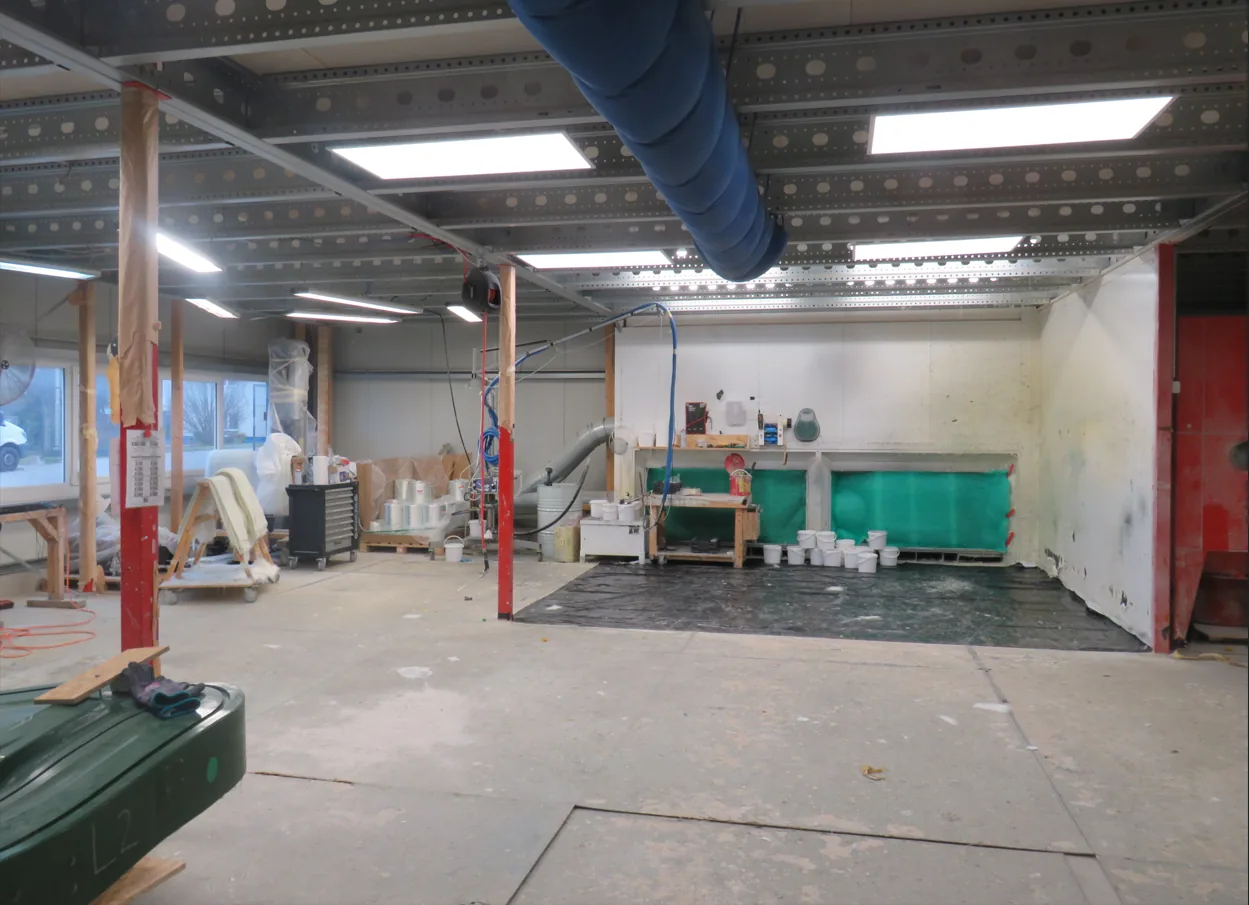
Our cells run in the hall of ACCENTFORM, a German shop that has made fibreglass, carbon and foam parts since 1998: theme-park figures, building facades, moulds and vehicle parts, one-offs and small series.
Every hard case reaches the cells first, so the system is built on real orders, not demos.
Moulds, foams, composites, fixtures, figures and series parts. Or a cell like this in your own shop.